Cool Info About How To Test The Polarity Of A Diode

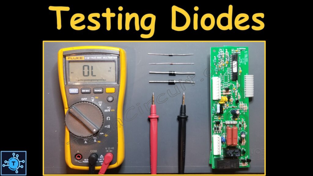
Testing Diodes With A Multimeter The Tech Circuit™
Unmasking the Diode
1. Why Bother with Polarity Anyway?
Alright, so you've got this little component called a diode. Looks simple enough, right? But before you go slapping it into your circuit, there's a crucial piece of information you need to know: its polarity. Think of it like a one-way street for electricity. It only allows current to flow in one direction. Get it backwards, and well, things might not work so well, or worse, you might let the smoke out (and nobody wants that!).
Knowing the polarity of your diode — which end is the anode (positive) and which is the cathode (negative) — is absolutely essential for it to function correctly in your circuit. Imagine trying to force a key into a lock the wrong way. Frustrating, isn't it? Same principle applies here. Correct polarity ensures the diode performs its intended function, whether it's rectifying AC voltage, protecting a sensitive component, or lighting up an LED.
So, why can't we just guess? Well, sometimes you can get lucky, but relying on chance is never a good strategy in electronics. Misidentifying the polarity could lead to circuit malfunction, component damage, or even a small explosion. Okay, maybe not a huge explosion, but still, avoiding drama is generally a good idea. Besides, taking a few minutes to properly identify the polarity can save you hours of troubleshooting and potential component replacement later on.
Basically, understanding and verifying diode polarity is like understanding the rules of the road. It keeps everything flowing smoothly and prevents accidents. It also saves you a ton of headaches and potential damage in the long run. So let's dive into how we can figure out which end is which!

How To Check A Diode Test Using Multimeter
Visual Clues
2. Decoding the Diode Body
Sometimes, the diode itself will give you a helping hand (or a helping marking, at least!). Many diodes have a band, stripe, or other marking near one end. This band almost always indicates the cathode, which is the negative side of the diode. Consider it the "exit" for the electrical current. Think of it like a little arrow pointing the direction the electrons can't go.
However, be careful! Not all diodes have these markings, and sometimes the markings can be faint or difficult to see, especially on older components. If you're working with salvaged parts or components that have been kicking around in your toolbox for a while, the markings might be worn off or obscured by dirt or grime. A good cleaning with a soft cloth and some isopropyl alcohol can sometimes reveal hidden markings, but proceed with caution.
Another visual clue can be the length of the leads (the wires coming out of the diode). Occasionally, the cathode lead will be slightly shorter than the anode lead. But, and this is a big "but," this isn't always the case. Manufacturing processes and lead trimming can sometimes make the leads the same length, or even reverse the lengths. So, while it's worth checking, don't rely on lead length as your sole indicator of polarity.
In summary, visual clues are a great starting point, but they shouldn't be your only source of information. Think of them as hints in a detective novel — useful, but not definitive. Always double-check your findings using other methods to ensure accuracy, especially if you're unsure about the reliability of the visual markings.
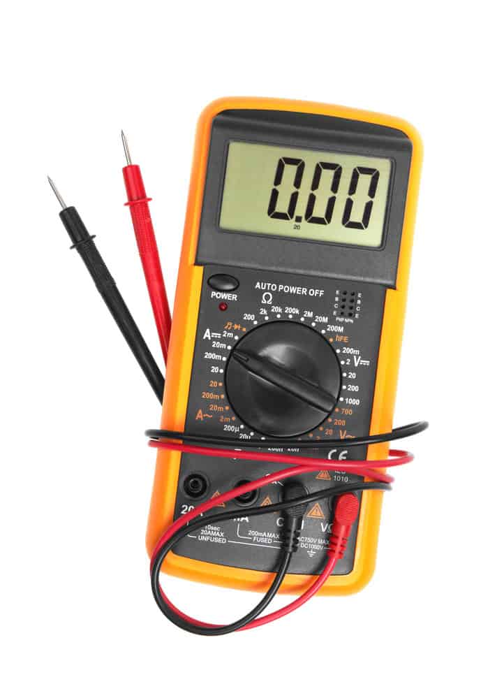
Comment Tester Les Diodes Fluke
The Multimeter Method
3. Using Your Multimeter to Solve the Polarity Puzzle
Ah, the multimeter! The trusty tool of every electronics enthusiast. It's like the Swiss Army knife of the electronics world, and it can definitely help us figure out the polarity of our diode. The most common method uses the diode test function, which is usually represented by a diode symbol on the multimeter's dial.
Here's how it works: Set your multimeter to the diode test function. Connect the red probe (positive) to one lead of the diode, and the black probe (negative) to the other lead. Observe the reading on the multimeter's display. If the diode is forward-biased (meaning the positive probe is connected to the anode and the negative probe is connected to the cathode), you should see a voltage reading, typically between 0.5V and 0.8V for a silicon diode. This is the forward voltage drop of the diode.
Now, reverse the probes. Connect the red probe to the other lead of the diode, and the black probe to the first lead. If the diode is reverse-biased (positive probe to cathode, negative probe to anode), you should see an "OL" or "1" on the multimeter's display, indicating an open circuit. This means that very little or no current is flowing through the diode.
If you get a voltage reading in one direction and an open circuit in the other, congratulations! You've successfully identified the polarity of your diode. The lead connected to the red probe when you got the voltage reading is the anode (positive), and the lead connected to the black probe is the cathode (negative). If you get similar readings in both directions (either both voltage readings or both open circuits), it could indicate that the diode is faulty or shorted. In that case, it's best to replace it with a new one.

Polarity Test Why It Is Important
Using a Breadboard and Resistor
4. The Safe and Easy Way to Test Diode Polarity
If you're feeling a bit more hands-on, you can use a breadboard, a resistor, and a power supply to test the diode. This method involves building a simple circuit and observing the current flow. It's a great way to visually confirm the polarity and get a better understanding of how a diode works in a circuit.
Here's the setup: Connect a resistor (around 1k ohm should be fine) in series with the diode on your breadboard. Connect one end of the resistor to the positive terminal of your power supply (typically 5V), and connect one end of the diode to the negative terminal. Now, observe the circuit. If the diode is forward-biased (anode connected to the resistor, cathode connected to the negative terminal), current will flow through the circuit. You can measure the voltage drop across the resistor to confirm this.
Now, reverse the diode in the circuit. Connect the cathode to the resistor and the anode to the negative terminal. If the diode is reverse-biased, very little or no current should flow through the circuit. You should see little to no voltage drop across the resistor. If you still see a significant voltage drop, it could indicate that the diode is leaky or damaged.
Remember to use a resistor in series with the diode to limit the current and protect it from damage. Connecting a diode directly to a power supply without a resistor can cause excessive current flow, which can overheat and destroy the diode. Safety first, always! This method provides a clear visual confirmation of the diode's behavior in a circuit, making it easier to understand the concept of polarity and current flow.

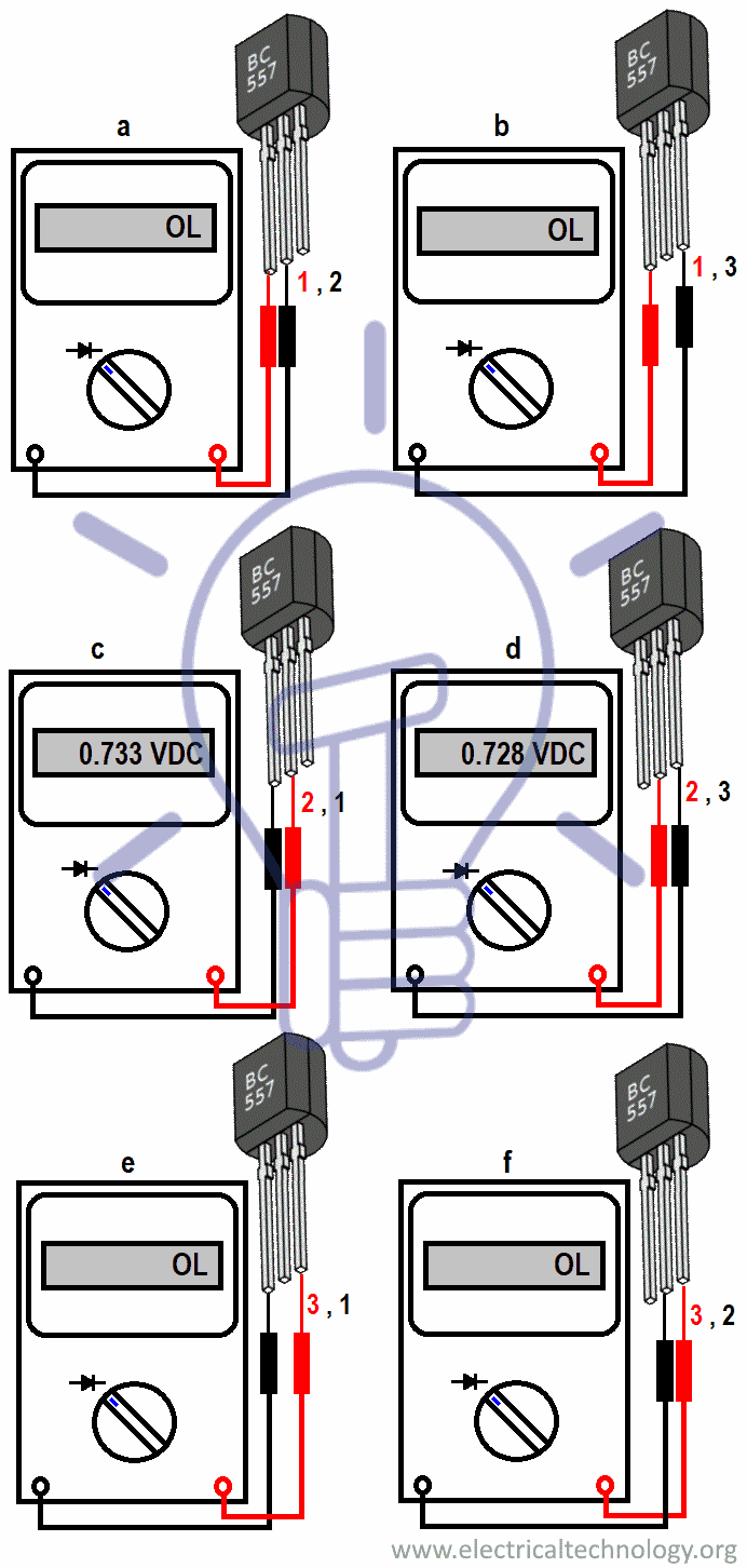
Transistor Polarity Identification
Safety First
5. Essential Safety Tips for Diode Testing
Electronics can be fun, but they can also be a bit dangerous if you're not careful. So, before you start poking around with diodes and multimeters, let's talk about safety. Always disconnect the power supply before making any changes to your circuit. This will prevent accidental shorts and potential electric shocks. Believe me, a little shock can really ruin your day.
When working with power supplies, make sure the voltage and current ratings are appropriate for the components you're using. Overpowering a diode can cause it to overheat and fail, potentially releasing harmful fumes or even causing a small explosion. It's always better to err on the side of caution and use a lower voltage power supply with a current-limiting resistor.
Also, be mindful of static electricity. Static discharge can damage sensitive electronic components, including diodes. Ground yourself before handling any components by touching a grounded metal object, such as a metal case of a computer or a grounded workbench. You can also use an anti-static wrist strap to continuously ground yourself.
Finally, wear appropriate safety glasses to protect your eyes from flying debris in case of a component failure. It's rare, but it can happen. And, of course, never work on electronics in a damp or wet environment. Water and electricity don't mix, and you definitely don't want to become part of the circuit. By following these simple safety tips, you can ensure a safe and enjoyable electronics experience.

Frequently Asked Questions (FAQs)
6. Your Diode Questions Answered
Q: What happens if I connect a diode backwards in a circuit?
A: If you connect a diode backwards, it won't conduct electricity. Depending on the circuit and the applied voltage, it might even damage the diode or other components in the circuit.
Q: Can I test a diode without a multimeter?
A: Yes, you can use the breadboard, resistor, and power supply method described above. However, a multimeter is generally the easiest and most accurate way to test a diode.
Q: What if my multimeter shows the same reading in both directions?
A: This usually indicates that the diode is either shorted (very low resistance in both directions) or open (very high resistance in both directions) and needs to be replaced.
Q: Are there different types of diodes, and does it affect polarity testing?
A: Yes, there are many types of diodes (Zener, Schottky, LEDs, etc.). The basic polarity testing methods apply to most standard diodes. However, Zener diodes and LEDs might have slightly different forward voltage drops. It's always a good idea to consult the datasheet for the specific diode you're testing.